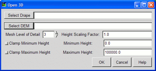
Select Drape and DEM | Mesh Level of Detail | Height Scaling Factor | Height Clamping

Displaying a raster in 3D requires two components. One is the drape image. The image to be displayed in 3D. The other component is the raster used as a source of elevation information (the DEM raster). The Open 3D dialog contains two embedded file selectors, one for selecting the drape image and one for selecting the DEM raster. Any TerraLook supported raster format can be used for the drape and the DEM. Supported raster formats are discussed in the File Access help topic.
Once selected TerraLook will create a 3D mesh over which to drape the drape image, based on elevation values from the DEM image. The density of the mesh is determined by the DEM Level of Detail control described later, but it is typically at substantially lower resolution than the drape image. Each mesh location is sampled from the DEM raster. If the location lies outside the DEM raster a value of zero is assumed.
It is not necessary for the drape and DEM images to have the same resolution or the same exact region; however, areas of the drape image lying outside the DEM will not have proper elevations assigned. Areas of the DEM outside the drape image will not be used. The coordinate system of the drape and DEM images should be compatible. TerraLook does not check this, so if the coordinate systems are different it is likely that no overlap will occur, or the elevations selected will be inappropriate.
The Mesh Level of Detail selector allows control over the density of the elevation mesh. A highly refined mesh will result in more accurate geometry, with one mesh point per drape pixel being the most refined the mesh can be (at level 8). The least refined mesh (normally used for 2D display) has only one mesh point at each corner of the 256x256 drape tiles, and is mesh level of detail 0.
Highly refined meshes take alot more memory, and will generally slow down redraws substantially. The default mesh density (level of detail 3) has one mesh vertex every 32 pixels. Level of details in excess of 5 (one mesh vertex every 8 pixels) can become painfully slow even on accelerated systems.
The height scaling factor is a multiplier applied to all elevations. A value of one gives a physically realistic display if the elevations are in the same units as the image georeferencing (ie. meters). It may be desirable to exaggerate the elevations to make 3D effects more visible by setting a scaling factor greater than one.
In some cases elevations are in different units, and the scaling factor can be used to correct for this. For instance, if the georeferenced display is in meters, but the elevations are in decimeters, a scaling factor of 0.1 will correct things.
The toggles for clamping minimum and maximum height can be used to restrict the range of mesh heights, according to the values in their corresponding text fields. This can be useful if the raster used as a DEM has invalid points that TerraLook is treating as valid data. This clamping is a one-time operation that acts on the data as it is read in to set the mesh values; it does not affect scaling operations that act on the view as a result of key-press events.
Once the OK button is hit, a new raster layer will be created, with associated 3D mesh values. Depending on the level of detail selected for the mesh this may take some time.